Videoscopes and Borescopes
Gas Transmission
Remote Visual Inspection Challenges in Natural Gas Service Lines
Remote Visual Inspection Challenges in Natural Gas Service Lines
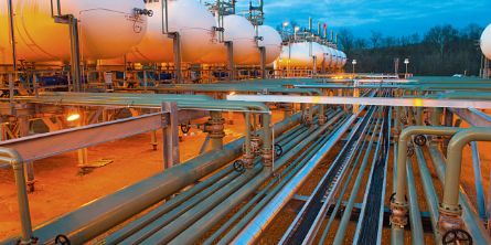
Natural gas pipelines transport more than 25 percent of the energy consumed in the United States, making them an important and pervasive component of our energy transportation system. These pipelines range in size and length depending on where along the stream they are located. Here, we are highlighting downstream natural gas service lines.
To service and provide natural gas to residential areas, distribution lines run parallel to the roadways in these neighborhoods. Service lines connect this distribution line with the gas meter on a property. These service lines have a smaller inside diameter (ID) than the distribution line as they are only servicing one property per line.
As with all pipelines, these service lines need to be inspected to determine whether a leak is currently happening or is likely to occur in the near future. This has recently become a larger concern given the age of some service lines. Many older service lines were made of cast iron, and they can crack and corrode, resulting in natural gas leaks in these residential areas. Gas leaks can have damaging consequences, especially in densely populated residential areas. The service lines must therefore be regularly inspected using nondestructive testing (NDT) or remote visual inspection (RVI) methods to help ensure continuing safety.
RVI technologies allow an inspector to see whether cracks exist on the inside of these service lines. A hairline crack is all that is needed to cause a leak, making image quality a critical factor in a visual inspection. The higher resolution the image is, the easier and quicker it is to reliably recognize the presence of a crack. An RVI product that delivers a high-resolution image requires a bright light source, high-quality optics, the latest imaging sensor technology and effective image reproduction.
RVI videoscopes used in service line inspections must have a combination of features to be used successfully. For example, they require a large focal range to see the interior wall and down the length of the entire pipe for navigation. Small-diameter insertion tubes that are very long are an advantage as they can reach farther into service line piping that may only have limited access points. The insertion tube and tip must be durable and provide a clear view inside dark spaces. Image clarity is crucial when inspecting a service line for cracks and general signs of wear because missing cracks or other discontinuities can compromise the line’s safety.
When cast iron service lines get too old, they are replaced with plastic pipelines. Plastic is a safer alternative to cast iron because it’s less susceptible to corrosion and cracking over the long term. However, plastic service lines create a new set of challenges for safety inspectors using RVI for the irinspections.
An ID of 0.5 in. (12.7 mm) is common in plastic pipelines, and the plastic pipe’s fittings pose additional challenges. When a visual inspection occurs in a metal pipe (cast iron or not), the ID will usually remain consistent. Whether the joints were secured by a fitting that existed around the exterior of the pipe or were welded together, the ID is largely unaffected. The plastic pipes used in service line replacements are welded by heat fusion, which can create large weld joints in the interior of the pipe and dramatically reduce the ID at the bends and joints. This welding process can reduce the effective ID at these joints down to 0.25 in. (6.35 mm).
There are many RVI products available for pipe inspection. However, the reduction in ID at the weld joints prevents industrial videoscopes with large-diameter insertion tubes from fitting through. This means that of all the differences between industrial videoscope types, the diameter of the insertion tube is the most limiting factor for this specific inspection. With the ID of these plastic pipes reduced to around 0.25 in., the outside diameter (OD) of a videoscope needs to be slightly smaller at 0.23 to 0.25 in. (5.8 mm to 6.35 mm).
As mentioned above, cracks and general signs of wear are the main targets for this inspection. Cracks are of special concern given that a hairline crack is enough to compromise the integrity of the pipe wall and cause a leak. To be able to see and discern a hairline crack, image clarity is crucial. The lighting, lensing, imaging chip, and image reproduction all need to work together to create a high-resolution image. This is already difficult, but even more so when we are dealing with insertion tubes with a diameter of at or below 8 mm.
One of the biggest hurdles in generating clear RVI images is getting enough light to the target and then back to the imaging chip. RVI is almost exclusively performed in enclosed areas where the only source of light is the videoscope itself. Given size limitations, the only way to increase the amount of light onto a pipe’s interior wall is by increasing the intensity of the light. Once the light bounces off the interior of the pipe it needs to pass through the lensing onto the imaging chip. The lensing needs to be as big as possible to allow as much light through while still leaving room for the light transmission in an 8 mm or smaller space.
Another variable to consider in an industrial videoscope is the focal range. The focal range is defined as the distance from the lensing to where the item or area of interest will be in focus. The unique requirement for this application is that the wall of the pipe immediately next to the lensing must remain in focus for the close-up inspection of cracks while areas farther away must also remain in focus for navigational purposes. Lens design is critical here. One way to create a focus that starts so close to the lensing is by decreasing the aperture. The aperture is the hole in the center of a lens system that allows light to pass through. So again, the difficulty of creating a high-clarity image is being limited by the requirements of the situation.
The lensing is on the end of the insertion tube. In simple terms, the insertion tube is a long cable that allows the lensing to be inserted and pushed through the pipe. The construction of the insertion tube enables the user to manually push it through a pipe without it coiling, while retaining the flexibility required to navigate bends or turns in the pipeline. The rigidity needed to be able to push along the pipe is significant, since the lengths of the pipe needing inspection can reach 100 ft (30.5 m).
Generating a very clear digital image starts with adequate lighting. To achieve this, some videoscopes utilize a bright macro-LED in the base to generate the light that then gets carried through the insertion tube using a fiber-optic bundle. To achieve maximum brightness at longer lengths, other models utilize a laser or laser-diode in the base. This helps ensure that enough light reaches the target even after having traveled through 100 ft of fiber-optic cable.
The next step in generating a high-quality image is for the light to pass through the lensing. Lens system design is complicated and time-consuming, and it is difficult to guarantee an image that is free from defects and artifacts. Another concern is the quality of the lens manufacturing process itself. A good lens design will not matter if sub-par lensing is being used. This is crucial when designing lensing that can either focus as close as 2 mm away or at an effective infinite distance.
The next component in the imaging process is the chip used to capture the image. Image sensor chips with the most pixels in a small size are important given the size limitation concerns when trying to generate a clear image.
Manufacturing a high-quality imaging system is difficult enough. Compound onto this the requirement of navigating through a natural gas pipeline. Insertion tubes must be able to maintain the flexibility needed to navigate around corners while providing enough pushing power to allow the insertion tube to travel through the pipe.
Also, the light guide fiber material is improved to increase anti-radiation durability and the illumination output from the light source is much brighter than with conventional industrial endoscopes. Even if it is exposed to radiation and damaged, the VIDEOSCOPE-XT can still illuminate enough to produce better images than conventional industrial endoscopes.
These improvements make the insertion tube of VIDEOSCOPE-XT now 1.7 times stronger than the previous generation. For example, the previous generation system must typically be exchanged every 3 to 6 months. In comparison, the VIDEOSCOPE-XT exchange frequency is every 5 to 10 months. Moreover, if the VIDEOSCOPE-XT is damaged, its main unit including the LCD monitor can remain in service. Only the scope unit needs to be exchanged.
- HD quality solid state imaging device that is resistant to radiation
- Low transmission loss light guide fiber (resistant to radiation)
- High intensity laser-diode light source
- Detachable scope unit
